Articles
How To Store Batteries
Modified: April 23, 2024
Looking for articles on how to store batteries? Discover expert tips and tricks for proper battery storage to ensure longevity and optimum performance.
(Many of the links in this article redirect to a specific reviewed product. Your purchase of these products through affiliate links helps to generate commission for Storables.com, at no extra cost. Learn more)
Introduction
Batteries are a vital part of our daily lives. From powering our smartphones and laptops to running various household appliances, batteries prove their usefulness time and again. However, when it comes to battery storage, many people are unaware of the best practices to ensure their longevity and performance. Proper battery storage is crucial to prevent leakage, degradation, and even potential hazards.
In this article, we will explore the importance of battery storage and provide some valuable tips and guidelines to help you properly store different types of batteries. Whether you are storing alkaline batteries, lithium-ion batteries, NiMH batteries, lead-acid batteries, rechargeable batteries, or button cell batteries, following the right storage practices will go a long way in preserving their shelf life and maximizing their efficiency.
Before we dive into the specifics of storing each type of battery, it is important to understand why proper battery storage is essential.
Firstly, storing batteries correctly helps prevent leakage. When batteries are stored in extreme temperatures or in close proximity to other metal objects, the risk of leakage increases. Leaked batteries not only result in wasted energy but can also cause damage to the devices they are used in.
Secondly, proper storage ensures that batteries retain their charge for longer periods. This is especially important for rechargeable batteries, as they lose their charge over time even when not in use. By following the right storage practices, you can extend the shelf life of your batteries and ensure they are ready for use when needed.
Lastly, proper battery storage is crucial for safety reasons. Batteries contain potentially hazardous chemicals, and mishandling or improper storage can lead to accidents and injuries. By storing batteries correctly, you can minimize the risk of fire, explosion, or any other safety hazards.
Now that we understand the importance of battery storage, let’s explore the factors to consider before storing batteries.
Key Takeaways:
- Proper battery storage is essential for maximizing lifespan, performance, and safety. Storing batteries in a cool, dry place, avoiding extreme temperatures, and regular inspection can prevent leakage, corrosion, and potential hazards.
- Following manufacturer guidelines and local regulations for battery disposal ensures environmentally friendly and safe disposal. Recycling batteries, separating by type, and utilizing collection programs contribute to sustainability and a greener future.
Read more: How To Store A Battery
Importance of Battery Storage
Battery storage plays a vital role in maintaining the performance, longevity, and safety of batteries. Whether you are storing batteries for long-term use or keeping backups for emergencies, following proper storage practices is crucial. Here are a few reasons why battery storage is important:
- Prolongs Battery Life: Proper storage can extend the shelf life of batteries, allowing them to retain their charge for longer periods. This is particularly important for rechargeable batteries, as they tend to self-discharge over time. By storing batteries correctly, you can maximize their lifespan and ensure they are usable when needed.
- Prevents Leakage: One of the main reasons for battery leakage is improper storage. When batteries are exposed to extreme temperatures or stored in close proximity to other metal objects, the risk of leakage increases. Not only does leakage result in wasted energy, but it can also damage the devices they are used in. By storing batteries in a cool and dry place, you reduce the likelihood of leakage.
- Ensures Optimal Performance: Some batteries, such as lithium-ion batteries, are sensitive to temperature fluctuations. Storing them in extreme hot or cold conditions can negatively impact their performance. By storing batteries in a controlled environment, you help maintain their optimal performance and prevent any performance degradation.
- Preserves Safety: Batteries contain chemicals and can pose safety risks if mishandled or stored improperly. Storing batteries in a safe and secure manner reduces the risk of accidents, such as fire or explosion. It is important to store batteries away from flammable materials and in a location where they cannot be easily damaged or punctured.
- Saves Money: Proper battery storage can save you money in the long run. By extending the lifespan of your batteries, you reduce the need for frequent replacements. Additionally, by preventing leakage and maintaining optimal performance, you avoid potential damage to devices, which can be costly to repair or replace.
Overall, proper battery storage is essential for maximizing the lifespan, performance, and safety of batteries. By following the best practices for storage and considering the specific requirements of different types of batteries, you can ensure that your batteries are always ready for use when you need them.
Factors to Consider Before Storing Batteries
Before you store batteries, there are a few important factors to consider to ensure their longevity and safety. By taking these factors into account, you can create an ideal storage environment for your batteries. Here are some factors to consider before storing batteries:
- Temperature: High temperatures can accelerate the self-discharge process of batteries, causing them to lose their charge more quickly. On the other hand, extremely cold temperatures can also affect battery performance. It is recommended to store batteries in a cool and dry place, preferably around 15 to 20 degrees Celsius (59 to 68 degrees Fahrenheit).
- Avoid Extreme Conditions: Extreme temperatures and humidity can have a negative impact on batteries. It is important to avoid storing batteries in areas that are too hot, too cold, or prone to high humidity. Avoid locations such as garages, attics, or basements where temperatures can fluctuate significantly.
- Battery Capacity: Before storing batteries, it is advisable to check their remaining capacity. Discharging batteries partially can help prevent them from self-discharging completely during storage. However, it is essential to keep in mind that some rechargeable batteries, such as lithium-ion batteries, should be stored at around 50% capacity for optimal shelf life.
- Battery Insulation: To prevent accidental short-circuits and potential hazards, it is important to store batteries in their original packaging or using insulating materials. This helps protect the battery terminals from making contact with metal objects or each other.
- Avoid Mixing Battery Types: Mixing different types of batteries, such as alkaline and rechargeable batteries, can lead to issues. Different types of batteries have different voltage levels, and mixing them can result in imbalances and potential damage. Always store batteries of the same type together.
- Keep Away from Metal Objects: Storing batteries near metal objects can increase the risk of short-circuits or accidental discharge. Keep batteries away from keys, coins, or other metal items that could potentially come into contact with the battery terminals.
- Battery Age: It is essential to consider the age of the batteries before storing them. Older batteries tend to have a higher self-discharge rate and may not retain their charge as well as newer ones. If you have older batteries with low capacity, it might be better to recycle them rather than store them.
By considering these factors and implementing the appropriate storage practices, you can ensure that your batteries stay in good condition and are ready for use when needed. In the next sections, we will explore the specific best practices for storing different types of batteries.
Best Practices for Storing Batteries
Proper battery storage is crucial for maintaining their performance and lifespan. Regardless of the type of battery you are storing, following these best practices will help ensure that they remain in good condition and are ready for use when needed:
- Store in a Cool, Dry Place: As mentioned earlier, storing batteries in a cool and dry environment is essential. High temperatures can lead to accelerated self-discharge, while excessive humidity can cause corrosion and degradation. Find a storage location that is away from direct sunlight, heat sources, and areas prone to moisture.
- Remove Batteries from Devices: If you plan to store devices for an extended period of time, remove the batteries from them. This reduces the risk of internal damage to the devices in case of leakage. Additionally, storing batteries separately prevents accidental discharging due to power-draining devices.
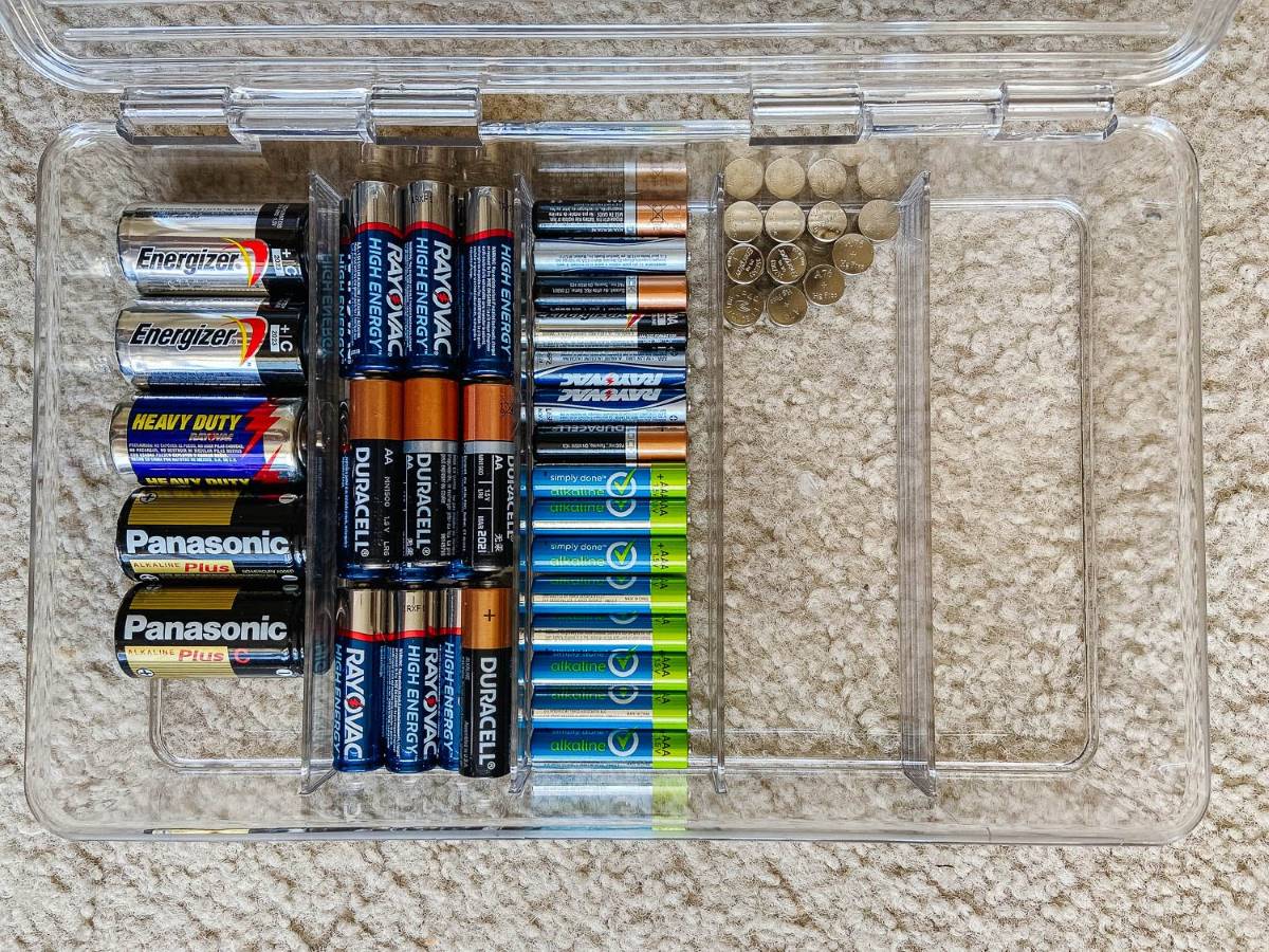
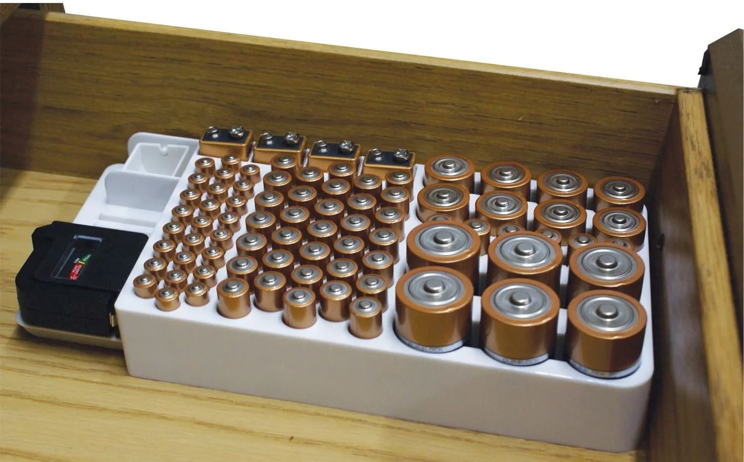
- Use Original Packaging: If possible, store batteries in their original packaging. Battery packaging is designed to protect them from moisture, dust, and external damage. If the original packaging is not available, use separate containers or storage compartments to keep the batteries organized and protected.
- Avoid Freezing Temperatures: While it is important to store batteries in a cool place, it is equally important to avoid freezing temperatures. Extremely low temperatures can adversely affect battery performance and may even cause irreversible damage. Protect batteries from freezing by storing them in insulated containers or areas that do not dip below freezing point.
- Check and Rotate: Regularly check the batteries you have stored to ensure they are still in good condition. This includes checking for any signs of leakage, corrosion, or expired batteries. If you have multiple batteries in storage, practice rotation by placing the newer ones at the back and using the older ones first.
- Ensure Proper Battery Charging: If you are storing rechargeable batteries, make sure they are charged adequately before storage. Storing batteries at a low charge level can lead to permanent capacity loss. Follow the manufacturer’s guidelines for proper charging and avoid overcharging, as it can also degrade the battery’s performance over time.
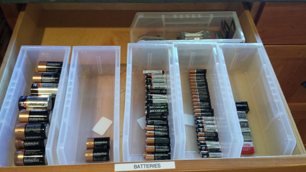
- Label Battery Storage: If you have various types of batteries in storage, it is helpful to label the containers or compartments to keep them organized. This will make it easier to locate specific batteries when needed and prevent mix-ups or accidental usage of incompatible batteries.
- Keep Out of Reach of Children and Pets: Batteries can be hazardous if swallowed or mishandled. Ensure that storage locations are out of reach of children and pets to prevent accidental ingestion or contact. Consider using child-proof containers or storing batteries in locked cabinets or drawers.
By following these best practices, you can ensure that your batteries remain in good condition and perform optimally when you need them. Now, let’s explore the specific storage guidelines for different types of batteries, including alkaline batteries, lithium-ion batteries, NiMH batteries, lead-acid batteries, rechargeable batteries, and button cell batteries.
Storing Alkaline Batteries
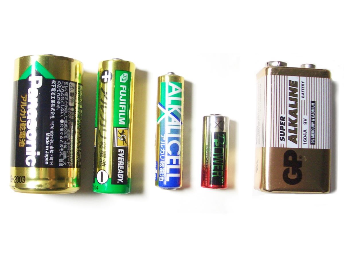
Alkaline batteries are commonly used in household devices, such as remote controls, toys, and flashlights. When storing alkaline batteries, it is important to follow these guidelines:
- Check Expiry Date: Before storing alkaline batteries, check the expiry date. Expired alkaline batteries may have reduced performance and can potentially leak or cause damage. Dispose of any expired batteries properly.
- Store at Room Temperature: Alkaline batteries should be stored at room temperature, ideally between 20 to 25 degrees Celsius (68 to 77 degrees Fahrenheit). Avoid extreme temperature fluctuations, as they can impact battery performance and lifespan.
- Avoid High Humidity: Alkaline batteries are sensitive to moisture, so it is important to store them in a dry environment. High humidity can lead to corrosion and reduce battery performance. Keep them away from areas with high moisture, such as bathrooms or damp basements.
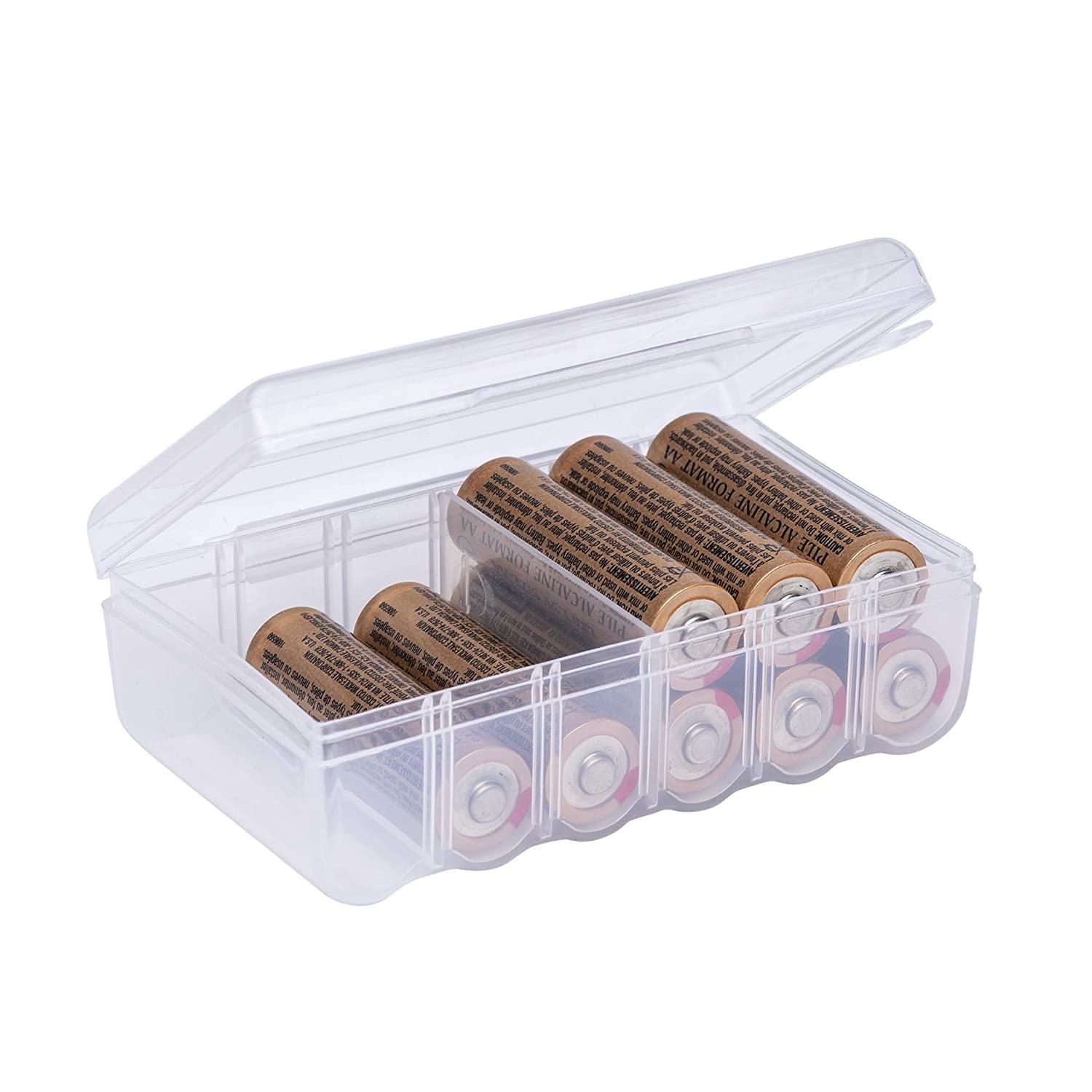
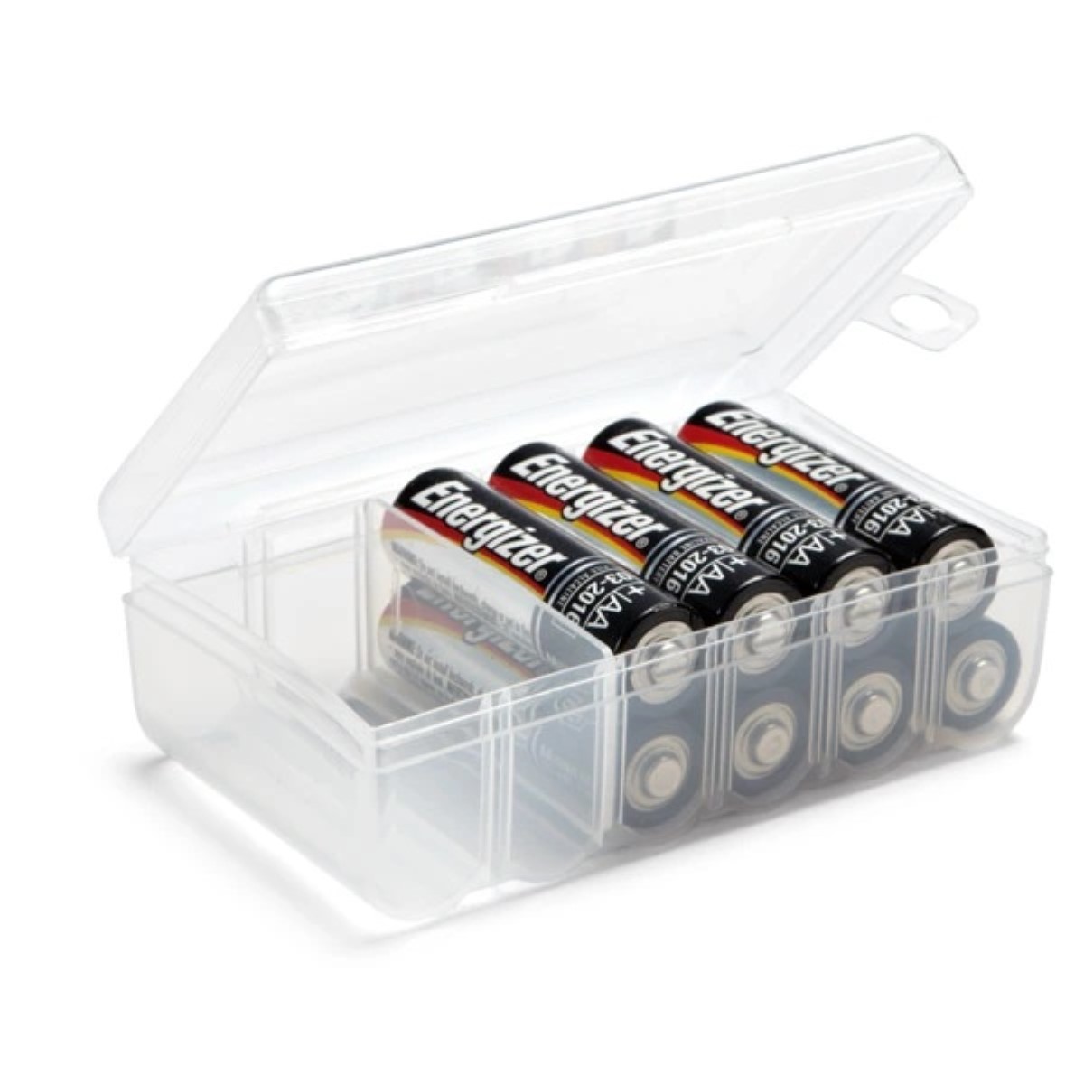
- Store in Original Packaging or Separately: If possible, store alkaline batteries in their original packaging to protect them from dust, moisture, and accidental contact with metal objects. If the original packaging is not available, store them separately or use battery storage cases or organizers designed for this purpose.
- Avoid Mixing with Other Batteries: Do not mix alkaline batteries with different types of batteries or batteries of varying ages. Mixing different batteries can result in imbalances and potentially cause damage. Always store alkaline batteries separately.
- Check for Leakage Regularly: Regularly inspect stored alkaline batteries for any signs of leakage. If you notice any leakage, dispose of the batteries properly and clean the storage area thoroughly to prevent any damage to surrounding objects.
- Keep Out of Reach of Children: As with any type of battery, keep alkaline batteries out of reach of children. Store them in a secure location, such as a locked cabinet or a container that is not easily accessible to young children.
- Dispose of Damaged or Leaking Batteries: If you come across damaged or leaking alkaline batteries during storage, handle them with caution. Wear protective gloves and dispose of them following the appropriate guidelines for battery disposal in your area.
By following these guidelines, you can ensure that your alkaline batteries remain in good condition and maintain their performance for extended periods of time. Proper storage not only prevents leakage but also maximizes the lifespan of alkaline batteries. Continue reading to learn about storing other types of batteries, such as lithium-ion batteries, NiMH batteries, lead-acid batteries, rechargeable batteries, and button cell batteries.
Read more: How To Store New Batteries
Storing Lithium-ion Batteries
Lithium-ion batteries power many modern devices, including smartphones, laptops, and electric vehicles. When it comes to storing lithium-ion batteries, it is important to follow specific guidelines to ensure their safety and longevity. Here are some tips for storing lithium-ion batteries:
- Store at 50% Charge: Lithium-ion batteries should be stored at around 50% charge to maintain their optimal condition. Storing them at a full charge or completely drained can lead to capacity loss and reduce their overall lifespan.
- Choose a Cool Environment: Keep lithium-ion batteries in a cool environment, ideally between 15 to 25 degrees Celsius (59 to 77 degrees Fahrenheit). Avoid storing them in extremely hot or cold places, as extreme temperatures can damage the battery and affect performance.
- Avoid Proximity with Metal Objects: When storing lithium-ion batteries, ensure they are not in direct contact with metal objects. Metal can create short circuits, leading to safety hazards or battery damage. Use separate storage compartments, sleeves, or insulating materials to prevent any contact with metal.
- Avoid Humid Environments: Moisture can damage lithium-ion batteries. Store them in a dry environment and avoid exposing them to high humidity or areas prone to moisture. Moisture can lead to corrosion, which can potentially compromise the battery’s performance.
- Inspect Regularly: Regularly check stored lithium-ion batteries for any signs of damage, such as bulging, leakage, or unusual odors. If you notice any abnormalities, dispose of the battery properly and clean the storage area thoroughly before storing new batteries.
- Keep Out of Reach of Children: Like other batteries, lithium-ion batteries should be stored out of reach of children. They contain chemicals that can be harmful if mishandled or ingested. Store lithium-ion batteries in a secure location, away from the reach of young children.
- Avoid Storing for Extended Periods: Lithium-ion batteries are best used and charged regularly. If possible, try not to store them for extended periods without use. Regular usage and charging help optimize the battery’s performance and prevent capacity degradation.
- Dispose of Expired or Damaged Batteries: If you come across expired or damaged lithium-ion batteries during storage, dispose of them safely and according to the appropriate guidelines in your area. Contact your local recycling centers or battery disposal facilities for proper disposal methods.
By following these guidelines, you can ensure that your lithium-ion batteries remain in good condition and are ready for use when needed. Proper storage practices not only preserve battery life but also prevent potential hazards associated with lithium-ion batteries. Next, we will explore the best practices for storing NiMH batteries, lead-acid batteries, rechargeable batteries, and button cell batteries.
Storing NiMH Batteries
NiMH (Nickel Metal Hydride) batteries are commonly used in various devices, including cameras, flashlights, and portable electronics. Proper storage of NiMH batteries is important to maintain their performance and prolong their lifespan. Here are some guidelines for storing NiMH batteries:
- Store at a Partial Charge: Unlike lithium-ion batteries, NiMH batteries should be stored at a partial charge. It is recommended to store them at around 40-60% of their capacity. Storing them fully charged or completely drained can lead to decreased performance and overall battery health.
- Choose a Cool, Dry Location: NiMH batteries should be stored in a cool and dry place, ideally between 15 to 25 degrees Celsius (59 to 77 degrees Fahrenheit). Avoid exposure to extreme temperatures or high humidity, as this can affect their performance and cause degradation.
- Avoid Physical Damage: Handle NiMH batteries with care and avoid dropping or subjecting them to physical damage. Damaged batteries can leak or lose their charge more quickly. Inspect them before storage and, if you notice any physical damage, dispose of them properly.
- Keep Batteries in Original Packaging or Insulated Containers: Store NiMH batteries in their original packaging if available. If not, use insulated containers or separate compartments to prevent contact between batteries and with other metal objects. This helps prevent short circuits and potential hazards.
- Regularly Check for Leakage: NiMH batteries should be inspected regularly for signs of leakage, such as corrosion or liquid residue around the battery terminals. If leakage is detected, dispose of the battery properly and clean the storage area thoroughly to avoid damage to other stored batteries.
- Keep Out of Reach of Children: NiMH batteries, like any other battery, should be stored out of the reach of children. They can pose a hazard if mishandled or swallowed. Store NiMH batteries in a secure location away from the access of young children.
- Avoid Mixing Battery Types: Do not mix different types of batteries or batteries of different capacities when storing NiMH batteries. Mixing batteries can result in imbalances and potential damage to the devices. Store NiMH batteries separately from other battery types.
- Dispose of Expired or Damaged Batteries: If you come across expired or damaged NiMH batteries during storage, dispose of them properly. Check with local recycling centers or battery disposal facilities for guidance on how to dispose of NiMH batteries safely and in an environmentally friendly manner.
By following these guidelines, you can ensure that your NiMH batteries are stored properly and maintain their performance. With proper storage practices, NiMH batteries can be ready for use when you need them. Next, we will explore the best practices for storing lead-acid batteries, rechargeable batteries, and button cell batteries.
Store batteries in a cool, dry place at room temperature. Avoid storing them in extreme temperatures or direct sunlight, as this can reduce their performance and lifespan. Keep them in their original packaging or use a battery organizer to prevent contact with metal objects and potential short-circuiting.
Storing Lead-Acid Batteries
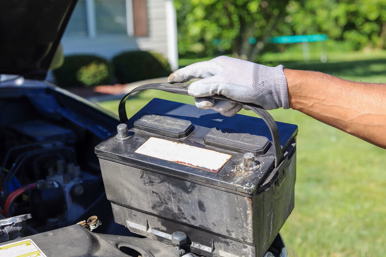
Lead-acid batteries are commonly used in vehicles, UPS systems, and renewable energy storage systems. Proper storage of lead-acid batteries is essential to ensure their longevity and performance. Here are some guidelines for storing lead-acid batteries:
- Store in a Well-Ventilated Area: Lead-acid batteries emit small amounts of hydrogen gas during charging. Therefore, it is crucial to store them in a well-ventilated area to prevent the buildup of potentially explosive gas. Avoid storing them in enclosed spaces or near sources of ignition.
- Maintain Proper Charge: Lead-acid batteries should be stored in a charged state to prevent sulfation and extend their lifespan. Periodically check the battery voltage and recharge if necessary to maintain the proper charge level.
- Avoid Extreme Temperatures: Lead-acid batteries are sensitive to temperature extremes. Avoid storing them in areas that can experience very hot or freezing temperatures, as this can affect their performance and lead to damage.
- Prevent Over-Discharge: Over-discharging lead-acid batteries can lead to irreversible damage and reduce their lifespan. If you plan on storing lead-acid batteries for an extended period, periodically recharge them to prevent over-discharge.
- Keep Battery Terminals Clean: Clean the battery terminals periodically to prevent corrosion. Corroded terminals can hinder the flow of electricity and affect battery performance. Use a mixture of baking soda and water or a battery terminal cleaner to clean the terminals if necessary.
- Store Upright: Lead-acid batteries should be stored in an upright position to prevent acid leakage. Storing them on their side or upside-down can cause the acid to leak, which is not only corrosive but also poses a safety hazard. Use battery racks or similar storage devices to keep them secure and upright.
- Store in a Dry Environment: Lead-acid batteries should be stored in a dry environment to prevent moisture-related issues. Moisture can lead to corrosion and reduce the lifespan of the batteries. Avoid storing them in damp or humid areas.
- Keep Out of Reach of Children: As with any type of battery, lead-acid batteries should be stored in a secure location out of the reach of children. They contain hazardous materials and should be handled with care.
- Dispose of Expired or Damaged Batteries: If you come across expired or damaged lead-acid batteries during storage, dispose of them properly. Contact a recycling center or follow the guidelines provided by your local authorities for the safe disposal of lead-acid batteries.
By following these guidelines, you can ensure that your lead-acid batteries are stored safely and maintained in good condition. Proper storage practices help prevent damage to the batteries and enhance their overall performance. Next, we will explore best practices for storing rechargeable batteries and button cell batteries.
Storing Rechargeable Batteries
Rechargeable batteries, such as NiMH (Nickel Metal Hydride) and lithium-ion batteries, are commonly used in a wide range of devices, including cameras, portable electronics, and power tools. Proper storage of rechargeable batteries is important to maintain their performance and prolong their lifespan. Here are some guidelines for storing rechargeable batteries:
- Charge Batteries Before Storage: Before storing rechargeable batteries, ensure they are adequately charged. Storing batteries in a partially discharged state can lead to capacity loss and reduced performance over time. Follow the manufacturer’s recommendations for the appropriate charge level before storage.
- Choose a Cool, Dry Location: Rechargeable batteries should be stored in a cool and dry environment, ideally between 15 to 25 degrees Celsius (59 to 77 degrees Fahrenheit). Extreme temperatures, both hot and cold, can affect battery performance and overall lifespan. Avoid exposing them to direct sunlight or other heat sources.
- Use Original Packaging or Insulated Containers: If available, store rechargeable batteries in their original packaging to protect them from dust and potential physical damage. Alternatively, use insulated containers or battery storage cases designed for rechargeable batteries to prevent contact with other metal objects and potential short circuits.
- Avoid Mixing Battery Types: Do not mix different types of rechargeable batteries or batteries of different capacities when storing them. Mixing batteries can result in imbalances and potential damage. Store each type of rechargeable battery separately.
- Inspect for Leakage and Damage: Regularly inspect stored rechargeable batteries for signs of leakage or physical damage. If you notice any leakage, corrosion, or swelling, dispose of the battery properly and clean the storage area thoroughly before storing new batteries.
- Charge Periodically: If you plan on storing rechargeable batteries for an extended period, consider charging them periodically to maintain their optimal charge level. This helps prevent self-discharge and ensures the batteries are ready for use when needed.
- Keep Out of Reach of Children: Rechargeable batteries, like any other batteries, should be stored out of the reach of children. They can be harmful if mishandled, swallowed, or short-circuited. Store them in a secure location, such as a locked cabinet or container.
- Dispose of Expired or Damaged Batteries: If you come across expired or damaged rechargeable batteries during storage, dispose of them properly. Check with local recycling centers or battery disposal facilities for guidance on how to dispose of rechargeable batteries safely and in an environmentally friendly manner.
By following these guidelines, you can ensure that your rechargeable batteries are stored properly and maintain their performance. Proper storage practices contribute to the longevity and overall health of the batteries. Next, we will explore best practices for storing button cell batteries.
Read more: How To Store Milwaukee Batteries
Storing Button Cell Batteries
Button cell batteries are small, coin-shaped batteries commonly used in devices such as watches, calculators, and hearing aids. When it comes to storing button cell batteries, it’s important to follow specific guidelines to ensure their safety and longevity. Here are some tips for storing button cell batteries:
- Check Expiry Date: Before storing button cell batteries, check the expiry date. Expired batteries may have reduced performance and can potentially leak or cause damage. Dispose of any expired batteries properly.
- Store in a Cool, Dry Place: Button cell batteries should be stored in a cool and dry environment, ideally between 20 to 25 degrees Celsius (68 to 77 degrees Fahrenheit). Avoid extreme temperature fluctuations, as they can impact battery performance and lifespan.
- Keep Terminals Clean: Clean the terminals of button cell batteries before storage to prevent corrosion. Corroded terminals can hinder the flow of electricity and affect battery performance. Use a clean cloth or cotton swab dipped in rubbing alcohol to gently clean the terminals if necessary.
- Store in Original Packaging or Insulated Containers: If possible, store button cell batteries in their original packaging to protect them from dust, moisture, and accidental contact with metal objects. If the original packaging is not available, store them separately or use small, insulating containers to prevent any contact with metal.
- Avoid Mixing Different Types of Batteries: Do not mix different types of button cell batteries when storing them. Mixing different battery types can lead to imbalances and potential damage. Store each type of battery separately.
- Regularly Check for Leakage: Periodically inspect stored button cell batteries for any signs of leakage or corrosion. If you notice any leakage, dispose of the batteries properly and clean the storage area thoroughly to prevent any damage to surrounding objects.
- Keep Out of Reach of Children: Button cell batteries are small and can present a choking hazard if ingested. Store them in a secure location out of the reach of children. Consider using child-proof containers or storing them in a locked cabinet or drawer.
- Dispose of Damaged or Expired Batteries: If you come across damaged or expired button cell batteries during storage, handle them with caution. Wear protective gloves and dispose of them following the appropriate guidelines for battery disposal in your area.
By following these guidelines, you can ensure that your button cell batteries remain in good condition and are ready for use when needed. Proper storage practices not only preserve battery life but also prevent potential hazards associated with button cell batteries. Remember to always handle and store batteries with care. With these best practices in mind, you can maintain the performance and longevity of your button cell batteries.
Tips for Extending Battery Shelf Life
Extending the shelf life of batteries is essential to ensure they remain reliable and ready for use when needed. Here are some helpful tips to help you extend the shelf life of your batteries:
- Properly Store Batteries: As mentioned earlier, storing batteries in a cool and dry place is key to preserving their shelf life. Avoid exposing them to high temperatures, humidity, or extreme temperature fluctuations. Store them in their original packaging or in separate compartments to prevent contact with other batteries or metal objects.
- Avoid Full Discharge: Fully discharging batteries can lead to capacity loss and reduce their overall lifespan. It is better to recharge batteries before they are completely drained, especially for rechargeable batteries.
- Regularly Use and Charge Rechargeable Batteries: Rechargeable batteries benefit from regular use and charging. If you have rechargeable batteries that are not in constant use, it is recommended to give them a full charge and discharge cycle at least once every few months to maintain their performance.
- Use the Right Charger: When charging rechargeable batteries, use the charger specifically designed for the battery type. Using the wrong charger can lead to overcharging or undercharging, affecting the battery’s performance and lifespan.
- Avoid Mixing Batteries: Mixing batteries of different types or different brands can result in imbalances and potential damage. It is best to use batteries of the same type, capacity, and age in the same device to ensure proper performance and longevity.
- Remove Batteries from Devices when Not in Use: If you are not going to use a device for an extended period, remove the batteries from it. This prevents energy drain and potential leakage, both of which can affect battery performance and lifespan.
- Keep Contact Surfaces Clean: Clean the battery contacts regularly to remove any dirt or corrosion that may interfere with the proper connection between the battery and the device. Use a clean cloth or cotton swab dipped in rubbing alcohol to gently clean the contacts.
- Avoid Extreme Temperatures during Use: When using devices powered by batteries, avoid subjecting them to extreme temperatures. Excessive heat or cold can degrade battery performance and may even cause damage to the battery or the device itself.
- Follow Manufacturer Guidelines: Always refer to the manufacturer’s guidelines and recommendations for proper usage, charging, and storage of specific battery types. Each battery type may have unique requirements, and following these guidelines can help maximize the shelf life and performance of the batteries.
- Dispose of Expired or Damaged Batteries Properly: Expired or damaged batteries should not be kept for an extended period, as they may pose safety hazards or leak harmful chemicals. Follow the proper guidelines for battery disposal in your area to ensure safe and environmentally friendly disposal.
By implementing these tips, you can extend the shelf life of your batteries and ensure they are always ready to power your devices when you need them. Remember, proper care and storage practices go a long way in maintaining battery performance and maximizing their lifespan.
Battery Disposal Guidelines
Proper battery disposal is essential for environmental protection and the safety of individuals. Different types of batteries require specific disposal methods due to their varying composition and potential hazards. Here are some general guidelines to follow when disposing of batteries:
- Separate Different Battery Types: Before disposing of batteries, it is important to separate them by type, such as alkaline, lithium-ion, NiMH, lead-acid, and button cell batteries. Mixing different types of batteries can lead to potential safety risks or environmental contamination.
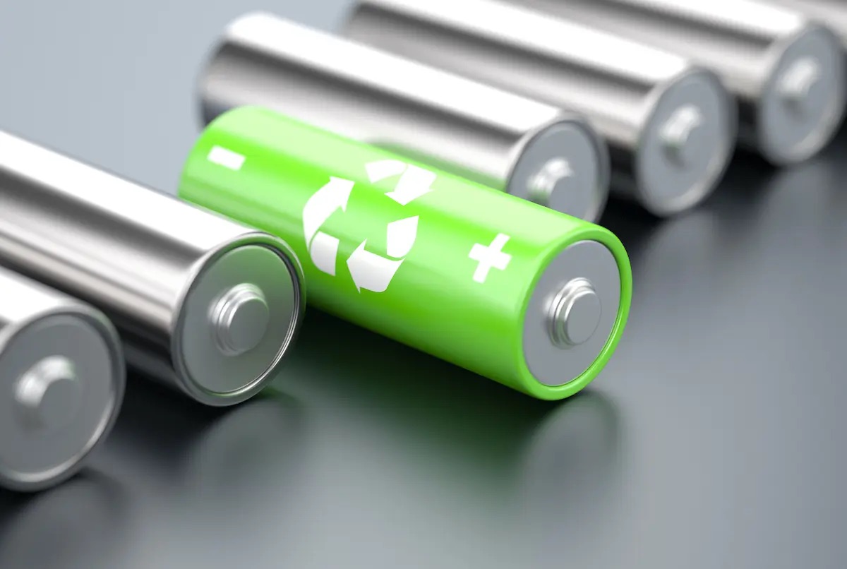
- Recycling is Recommended: Recycling batteries is the preferred method of disposal for most types of batteries. Many communities have dedicated recycling centers or designated drop-off points for battery recycling. Contact your local recycling facility or check with local government agencies for information on battery recycling in your area.
- Look for Battery Collection Programs: Some retailers and electronics stores offer collection programs for battery disposal. These programs ensure proper recycling or disposal of batteries in an environmentally friendly manner. Check with local stores or manufacturers for any available collection programs.
- Rechargeable Battery Recycling: Rechargeable batteries, such as lithium-ion batteries and NiMH batteries, often contain hazardous materials. It is important to recycle them to prevent environmental contamination. Many retailers or recycling centers accept rechargeable batteries for recycling.
- Button Cell Battery Disposal: Button cell batteries are small but can be harmful if ingested or mishandled. It is recommended to recycle button cell batteries rather than throw them in the trash. Many retailers and recycling centers have collection bins specifically for button cell batteries.
- Lead-Acid Battery Disposal: Lead-acid batteries, commonly used in vehicles and backup power systems, contain lead and sulfuric acid, making them hazardous. They should be taken to authorized recycling centers or facilities that can properly handle and dispose of them.
- Properly Package Damaged or Leaking Batteries: If you come across damaged or leaking batteries, handle them with caution. Wear gloves and place the batteries in a plastic bag or container to prevent any potential leakage. Contact local recycling or disposal facilities for guidance on how to dispose of damaged or leaking batteries.
- Follow Local Regulations: Battery disposal regulations may vary from one region to another. It is important to follow the specific guidelines and regulations set by your local government or environmental authorities regarding battery disposal. These regulations are in place to protect the environment and ensure safe disposal practices.
By following these battery disposal guidelines, you can help minimize the environmental impact of batteries and reduce potential hazards related to improper disposal. Remember, it is crucial to handle and dispose of batteries correctly to protect both our environment and our communities.
Conclusion
Proper battery storage is crucial for maintaining the performance, longevity, and safety of batteries. Whether you are storing alkaline batteries, lithium-ion batteries, NiMH batteries, lead-acid batteries, rechargeable batteries, or button cell batteries, following the right storage practices will go a long way in preserving their shelf life and maximizing their efficiency.
By storing batteries in a cool and dry place, avoiding extreme temperatures and humidity, and properly packaging them, you can prevent leakage, corrosion, and potential hazards. It is important to store batteries separately by type, avoid mixing different battery types or different ages, and ensure proper insulation to prevent short circuits.
Regularly checking batteries for leakage, corrosion, or expiration dates is essential. Dispose of expired or damaged batteries responsibly by recycling them through collection programs or designated recycling centers. Following local regulations and guidelines for battery disposal ensures that batteries are disposed of in an environmentally friendly and safe manner.
Remember, proper handling and storage practices for batteries not only extend their shelf life but also contribute to sustainability and the protection of our environment. Following the manufacturer’s recommendations and guidelines specific to each battery type will help you get the most out of your batteries and ensure they are ready for use when needed.
By implementing these best practices for battery storage and disposal, you can enjoy the full potential of your batteries, reduce waste, and contribute to a greener future.
Frequently Asked Questions about How To Store Batteries
Was this page helpful?
At Storables.com, we guarantee accurate and reliable information. Our content, validated by Expert Board Contributors, is crafted following stringent Editorial Policies. We're committed to providing you with well-researched, expert-backed insights for all your informational needs.


0 thoughts on “How To Store Batteries”